

At a parts transfer station, the scanner can show an occupied zone while the PLC still shows a clear approach. Before anybody redraws the zone, check what happens between the output terminal and the input card. A scanner that supplies discrete outputs leaves the station controller to interpret those signals. Polarity, input grouping and signal timing belong in the controls drawing from the start.
Start at the input card
Find the complete PLC input-module number and its input circuit. In the usual terminology, a sinking input takes current from a PNP sourcing output. A sourcing input supplies current to an NPN sinking output. Modules that support either arrangement can still share a common across several channels. Changing the common for one scanner may also affect sensors already connected to that group. Use the module diagram to decide whether the spare channels are suitable. DAIDISIKE’s NPN and PNP input pairing guide shows the two current paths and explains why choosing an output from the PLC’s brand name can lead to the wrong order.
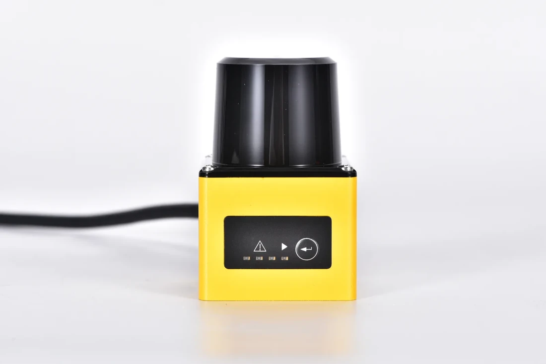
DLD05A3 industrial zone detection LiDAR
Give each input a job
The DLD05A3 switching output specifications list the DLD05A3-3N with NPN outputs and the DLD05A3-3P with PNP outputs. The series supplies three detection outputs and a separate device status signal. It stores up to sixteen zone sets with three zones in each set. On the input list, give each channel a physical meaning and state when that meaning applies. For example, a channel called Approach Occupied should identify the zone and the active set used during a carrier approach. Keep the status indication on its own line so it is available for troubleshooting.
An electrical match also depends on the input thresholds, supply and permissible load. Have the controls engineer compare the sensor’s output limits with the exact input card and use the scanner’s connector documentation. A generic three-wire sensor sketch cannot supply the pin assignments for this unit.
Watch the scanner and controller together
On a controlled process trial, note the expected PLC states with an empty approach, a carrier passing through and a carrier left in the transfer position. Include a separate row for an unavailable device, with the response defined from documented status behavior. An inactive detection channel by itself cannot distinguish an empty area from a failed signal path. If the station swaps zone sets, repeat the trial through that transition as well as with each set held steady.
Compare the PLC input trace with what the scanner reports. If a short event reaches the input but the station misses it, review the input filter and program timing with the controls engineer. If it never reaches the input, work back through polarity, supply and the signal circuit before changing the zone. This is an ordinary process detection interface. Personnel protection requires a separately selected and validated safety function.
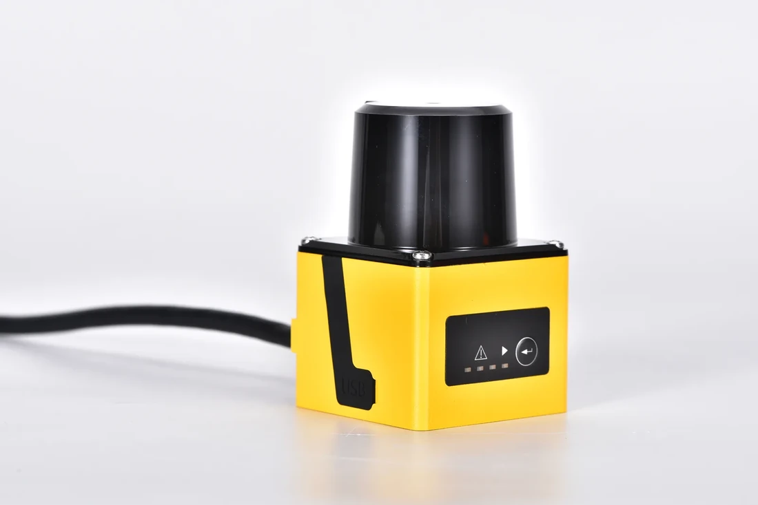
DLD05A3 sensor from a second angle
Matching a Zone Scanner to a Transfer Station PLC Input
